Magna Electro Castings is a manufacturing company that specializes in producing ferrous components, gray iron castings and Austempered Ductile Iron Castings ranging from 300 grams to 2000 kilograms. Magna adds value to their products by providing services like heat treatment, surface treatments, and machining, making them ready for assembly.
Additionally, Magna has an in-house CNC machine shop and other facilities for producing fully machined components. They have expertise in supplying safety requirement components in both casting and fully machined forms, meeting high standards for radiographic quality and metallurgical control.
To cater to low volume requirements, Magna has established a warehouse in the USA and ships containers bi-weekly. This allows them to provide just-in-time delivery to customers in the United States.
Bearing Cap Austempered Ductile Iron Castings
A bearing cap is a crucial component used in various mechanical systems to support rotating elements and facilitate smooth movement. It serves as a protective cover and enclosure for the bearing, which is responsible for reducing friction and supporting loads.
Typically made of durable materials such as steel or cast iron, the bearing cap is designed to withstand high pressures and extreme operating conditions. It is often bolted or secured tightly to the housing or frame, ensuring that the bearing remains securely in place.
The primary function of the bearing cap is to provide protection to the bearing, preventing contaminants from entering and damaging the internal components. It also helps to retain lubrication within the bearing, ensuring optimal performance and longevity.
In addition to its protective role, the bearing cap assists in maintaining proper alignment and positioning of the bearing within the system. It helps to distribute the load evenly, reducing stress and wear on the bearing and other related components.
Bearing caps come in various designs and configurations, depending on the specific application and type of bearing being used. They are commonly found in industrial machinery, automotive engines, construction equipment, and many other mechanical systems that involve rotational motion.
Overall, the bearing cap plays a critical role in ensuring the smooth operation and longevity of rotating elements, making it an essential component in numerous industries.
Frame Head Austempered Ductile Iron Castings
The frame head is a vital component in the construction of various structures, such as buildings, bridges, and vehicles. It is typically the main structural element that supports and distributes the loads throughout the frame.
In construction, the frame head refers to the uppermost horizontal beam or member at the top of a structural frame. It provides a connection point for vertical columns or beams, serving as a key element in the overall stability and integrity of the structure. The frame head helps to transfer the loads from the upper levels of the building or structure down to the foundation.
In the context of vehicles, the frame head is an important part of the chassis or frame structure. It forms the front section of the frame and provides a mounting point for the engine, front suspension, and other key components. The frame head in vehicles is designed to absorb impact forces in the event of a collision and help protect the occupants by maintaining the structural integrity of the vehicle.
The design and construction of frame heads vary depending on the specific application and structural requirements. They are typically made of strong and durable materials such as steel or reinforced concrete to ensure stability and load-bearing capacity.
In summary, the frame head is a crucial component in both building and vehicle construction, providing structural support, load distribution, and impact resistance. Its proper design and construction are essential for the overall strength and safety of the structure or vehicle.
Linear Yoke Austempered Ductile Iron Castings
A linear yoke is a mechanical component used in various systems to convert rotary motion into linear motion or vice versa. It is a type of actuator that consists of a yoke or carriage that moves along a linear path guided by a rail or track.
The linear yoke typically incorporates a motor or other power source that drives a rotary mechanism, such as a ball screw or a lead screw. As the rotary motion is transmitted to the linear yoke, it converts it into linear motion along the guided path.
Linear yokes are commonly used in applications where precise and controlled linear movement is required. They are utilized in industrial automation, robotics, CNC machines, 3D printers, packaging equipment, and various other systems that involve linear positioning or actuation.
The design and construction of linear yokes may vary depending on the specific application and requirements. They are often made of durable materials such as aluminum or steel to ensure strength and rigidity. The guiding rails or tracks can be linear bearings, profiled rails, or other types of linear motion guides, depending on the desired precision and load capacity.
Linear yokes offer advantages such as high positional accuracy, repeatability, and smooth motion. They provide a means to convert rotary motion into linear motion or control linear movement precisely, enabling automation and precise positioning in a wide range of industries and applications.
Pedestal for Trailer Suspension Austempered Ductile Iron Castings
A pedestal for trailer suspension is a component used in trailer systems to support and connect the suspension system to the trailer frame. It serves as a mounting point for the suspension components, such as the axle, leaf springs, airbags, or torsion axles.
The pedestal is typically a sturdy and rigid structure, often made of steel or other durable materials, capable of withstanding the loads and forces encountered during trailer operation. It is designed to securely hold and align the suspension components, ensuring proper functionality and weight distribution.
The pedestal is attached to the trailer frame through bolts or welds, providing a stable connection that allows the suspension system to effectively absorb and manage the dynamic forces experienced during towing or transportation.
The design and configuration of the pedestal may vary depending on the specific trailer application, load capacity, and suspension type. Some trailers may have a single pedestal at the center, while others may have multiple pedestals distributed along the frame.
The pedestal plays a crucial role in maintaining the stability, ride quality, and overall performance of the trailer suspension system. It helps to distribute the weight of the cargo evenly, minimizes vibrations and shocks, and contributes to the safe and smooth operation of the trailer.
In summary, a pedestal for trailer suspension is a structural component that supports and connects the suspension system to the trailer frame. It provides a secure mounting point for the suspension components, ensuring proper alignment, weight distribution, and overall performance of the trailer.
Pushrod for Railways Austempered Ductile Iron Castings
In the context of railways, a pushrod refers to a mechanical linkage used to transmit force or motion between different components in a train’s braking system. It is a critical part of the train’s braking mechanism and plays a role in applying the brakes to the wheels.
The pushrod is typically a metal rod or bar that connects the brake cylinder or brake actuator to the brake rigging or brake shoes. When the train operator activates the braking system, hydraulic or pneumatic pressure is applied to the brake cylinder or actuator. This pressure is then transferred through the pushrod, causing it to extend or retract. The movement of the pushrod is transmitted to the brake rigging, which in turn applies pressure to the brake shoes, resulting in the braking force being applied to the train’s wheels.
Pushrods in railway braking systems need to be robust and capable of withstanding high forces and repetitive motion. They are often made of strong and durable materials like steel or alloy to ensure reliability and longevity.
The design and configuration of pushrods may vary depending on the specific type of braking system used in the train. Different types of trains may utilize different braking technologies, such as air brakes, electro-pneumatic brakes, or regenerative brakes. The pushrod design will be tailored to suit the specific braking system employed.
Overall, pushrods are an integral part of the braking system in railway applications, allowing for the efficient and controlled application of braking force to ensure safe and reliable train operations.
Valve Bodies Austempered Ductile Iron Castings
Valve bodies are key components in various fluid control systems, including pipelines, industrial processes, and mechanical systems. They play a crucial role in regulating the flow, direction, and pressure of fluids (liquids or gases) within a system.
A valve body is the main housing or casing that contains the internal components of a valve. It provides the structural support and enclosure for the valve mechanism, including the valve stem, disc, seat, and other associated parts.
Valve bodies are typically made of durable materials, such as cast iron, steel, or various alloys, to withstand the pressures and temperatures encountered in different applications. They are designed to be leak-proof and resistant to corrosion, ensuring the integrity and reliability of the valve.
The design and configuration of valve bodies vary depending on the specific valve type and application. Different types of valves, such as gate valves, globe valves, ball valves, or butterfly valves, have distinct body designs to accommodate their specific operating mechanisms and flow control requirements.
Valve bodies can have various connection types, such as threaded, flanged, or welded, to facilitate their installation and integration into a system. They can also feature additional ports or outlets for auxiliary functions, such as pressure relief, draining, or instrumentation.
Overall, valve bodies are essential components in fluid control systems, providing the housing and support for the internal valve mechanism. Their design, material selection, and construction are critical factors in ensuring the proper functioning, reliability, and longevity of the valves in various industrial and mechanical applications.
Diffuser for Turbo Charger Industry
In the turbocharger industry, a diffuser is a vital component that is used to optimize the performance and efficiency of turbocharger systems. It is an integral part of the turbine housing and is located downstream of the turbine wheel.
The primary function of the diffuser is to convert the high-velocity exhaust gases exiting the turbine wheel into lower-velocity, higher-pressure gases before they enter the exhaust system. This conversion process is achieved by gradually expanding the flow area, which slows down the exhaust gases and increases their pressure.
The diffuser helps to recover energy from the exhaust gases and improve overall turbocharger efficiency. By reducing the velocity and increasing the pressure of the exhaust gases, the diffuser allows the turbine to extract more energy from the exhaust stream, resulting in increased turbine power and better turbocharger performance.
Designing an efficient diffuser involves careful consideration of factors such as the turbine wheel size, exhaust gas flow rate, and desired pressure ratio. Diffusers are typically engineered with aerodynamic principles in mind to minimize flow losses and ensure smooth gas flow transition.
Materials used in diffuser construction must be capable of withstanding high temperatures and pressures commonly encountered in turbocharger applications. Common materials include stainless steel or heat-resistant alloys.
Overall, the diffuser is a critical component in the turbocharger industry, optimizing exhaust gas flow and contributing to the efficiency and performance of the turbocharger system. By effectively converting high-velocity exhaust gases into higher-pressure energy, the diffuser plays a key role in enhancing the power output and overall effectiveness of turbochargers in a wide range of applications, including automotive, marine, and industrial sectors.
Upper Cover for Hydraulics Industry
In the hydraulics industry, the term “upper cover” typically refers to a protective or enclosing component used in hydraulic systems to cover and shield certain parts or areas. It helps to safeguard sensitive hydraulic components and prevent contaminants from entering the system.
The upper cover can be found in various hydraulic equipment and systems, including hydraulic pumps, valves, cylinders, reservoirs, and manifolds. It is often designed to fit over the top portion of the component or system, providing a protective barrier.
The primary purpose of the upper cover is to protect the internal hydraulic components from external elements such as dust, dirt, moisture, and debris. It helps to maintain the cleanliness and integrity of the hydraulic system, reducing the risk of damage, wear, and contamination.
Upper covers are typically made of durable materials that are resistant to corrosion, such as metals (e.g., steel or aluminum) or high-quality plastics. The material selection depends on factors like the application environment, operating conditions, and desired level of protection.
The design and features of upper covers may vary depending on the specific application and component being covered. Some upper covers may have openings or access points for maintenance and inspection purposes, while others may be fully enclosed.
Overall, the upper cover plays a crucial role in the hydraulics industry by providing protection and preserving the performance and longevity of hydraulic components and systems. It helps maintain the cleanliness and reliability of the hydraulic system, contributing to its efficient operation and minimizing the risk of breakdowns or malfunctions.
Sliding Sleeve for Transmission Industry
In the transmission industry, a sliding sleeve refers to a mechanical component used in manual or automated transmissions to engage and disengage gears or gear sets. It is an integral part of the shifting mechanism and facilitates the smooth transition between different gear ratios.
The sliding sleeve, also known as a synchronizer sleeve or shift collar, is typically a cylindrical component that slides along the transmission shaft or hub. It has teeth or splines on its inner surface that mesh with corresponding teeth or splines on the gear or gear set.
During gear shifting, the sliding sleeve moves to engage or disengage the desired gear. When the sleeve is positioned to engage a gear, it locks onto the gear’s teeth or splines, allowing power transmission from the input shaft to the output shaft. Conversely, when the sleeve is moved to disengage a gear, it separates from the gear’s teeth, interrupting power transmission and enabling a smooth gear change.
The design and construction of sliding sleeves vary depending on the specific transmission system and gear configuration. They are typically made of durable materials such as steel or bronze to withstand the high loads and stresses involved in gear shifting.
Sliding sleeves incorporate features to ensure proper synchronization and smooth engagement of gears. These may include frictional surfaces, springs, or other mechanisms that aid in equalizing speeds and reducing shift shock during gear changes.
Overall, sliding sleeves are essential components in transmission systems, enabling efficient gear shifting and smooth power transmission. Their design and functionality are crucial for achieving accurate and reliable gear changes, enhancing the performance and longevity of manual and automated transmissions in various automotive and industrial applications.
Air Manifolder Austempered Ductile Iron Castings
In the locomotive industry, an air manifolder, also known as an air manifold or air distribution manifold, refers to a component used in the air brake system of a locomotive. It is responsible for distributing compressed air to various pneumatic devices and components throughout the locomotive.
The air manifolder acts as a central hub for the distribution of air from the locomotive’s air reservoirs to the different brake valves, cylinders, and other pneumatic devices. It is typically a complex assembly that includes multiple ports, valves, and connections to facilitate the precise control and delivery of air pressure.
The design and configuration of air manifolders can vary depending on the specific locomotive model and brake system requirements. They are typically constructed of durable materials such as steel or aluminum, ensuring reliability and longevity in the demanding locomotive environment.
Air manifolders incorporate valves, regulators, and other components to control and regulate the flow and pressure of compressed air. They may also include pressure gauges or indicators to monitor the air pressure within the system.
Proper functioning of the air manifolder is crucial for the safe operation of the locomotive’s air brake system. It ensures the timely and efficient application and release of brakes, allowing the locomotive to slow down, stop, and maintain control during operation.
Overall, the air manifolder plays a critical role in the locomotive industry by providing the central distribution point for compressed air in the air brake system. It enables effective control and operation of the brakes, contributing to the safety and performance of locomotives in railway transportation.
Axial Bearing for the Turbo Charger
In the context of a turbocharger, an axial bearing refers to a specific type of bearing that supports the axial or thrust load generated by the rotating components within the turbocharger. It helps to maintain stability and proper alignment of the turbocharger’s rotating assembly.
The axial bearing is typically located at the rear or exhaust end of the turbocharger, supporting the axial thrust load exerted by the turbine wheel. This bearing allows the turbine wheel to rotate smoothly while accommodating the axial forces generated by the exhaust gas flow.
The axial bearing is designed to handle both the axial load and the high operating temperatures encountered in turbocharger applications. It is commonly constructed using materials that can withstand elevated temperatures and resist wear, such as high-quality steel or specialized alloys.
To ensure efficient operation and durability, the axial bearing may incorporate features such as ball bearings, roller bearings, or thrust washers. These elements help distribute the axial load evenly and reduce friction, allowing for smooth rotation and minimizing wear on the turbocharger components.
Proper lubrication is crucial for the performance and longevity of the axial bearing. Turbochargers often incorporate oil lubrication systems that deliver a controlled flow of lubricating oil to the bearing to reduce friction and dissipate heat.
In summary, the axial bearing in a turbocharger is a specialized bearing designed to support the axial thrust load generated by the rotating components. It helps maintain stability, proper alignment, and smooth rotation of the turbocharger’s turbine wheel, contributing to its overall performance and durability.
Bearing Cap for the Engine Industry
In the engine industry, a bearing cap is a component used to secure and retain the bearings within an engine’s crankshaft or camshaft assembly. It is an essential part of the engine’s bearing system, which provides support and reduces friction between the rotating shaft and the engine block.
The bearing cap is typically a rigid and durable structure, often made of cast iron or steel, that is bolted or fastened to the engine block. It covers and encloses the bearing shells, ensuring they remain in place and properly aligned with the crankshaft or camshaft.
The bearing cap serves several important functions. It provides structural support and rigidity to the bearings, preventing excessive movement or vibration that could lead to premature wear or failure. Additionally, it helps maintain the proper oil clearance between the bearings and the shaft, ensuring effective lubrication and reducing friction.
The design and configuration of bearing caps may vary depending on the specific engine design and application. They are engineered to withstand the loads and forces exerted on the bearings during engine operation, which can include high rotational speeds, varying temperatures, and significant pressures.
Bearing caps are precision-machined to ensure accurate alignment and fit with the engine block and bearings. They may incorporate features such as dowel pins, alignment marks, or tightening sequence indicators to facilitate proper installation and assembly.
Overall, the bearing cap is a critical component in the engine industry, providing secure retention and support for the bearings within the crankshaft or camshaft assembly. It contributes to the smooth and reliable operation of the engine, minimizing friction, and ensuring the longevity and performance of the engine’s rotating components.
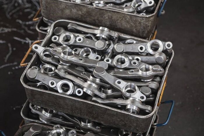
Rocker Bracket for the Engine Industry
In the engine industry, a rocker bracket, also known as a rocker arm bracket, is a component used in internal combustion engines to support and guide the rocker arms. It is typically located on the cylinder head or engine block and plays a crucial role in the engine’s valvetrain system.
The rocker bracket serves as a mounting point for the rocker arms, which are responsible for actuating the engine’s valves. It provides stability and proper alignment for the rocker arms, allowing them to pivot and transfer motion from the camshaft to the valves.
The design and configuration of rocker brackets can vary depending on the engine type and valvetrain system. They are often made of durable materials like cast iron, aluminum, or steel to withstand the forces and vibrations encountered in engine operation.
Rocker brackets are typically designed to accommodate multiple rocker arms, with each arm corresponding to an individual valve. They feature mounting holes or slots that align with the rocker arm shaft or pivot points, ensuring precise positioning and secure attachment.
Proper lubrication is crucial for the rocker bracket and rocker arm assembly. Many engines incorporate oil passages or channels within the bracket to supply lubricating oil to the rocker arms and reduce friction. Some rocker brackets also have oil grooves or reservoirs to facilitate oil distribution to the moving parts.
Rocker brackets play a significant role in controlling valve timing and ensuring proper valve operation in the engine. They contribute to the overall performance, efficiency, and longevity of the valvetrain system.
In summary, the rocker bracket is an important component in the engine industry, providing support and alignment for the rocker arms in the valvetrain system. It enables efficient transfer of motion from the camshaft to the valves, ensuring accurate valve timing and optimal engine performance.
Coupling Yoke for the Off-Highway Industry
In the off-highway industry, a coupling yoke refers to a component used in drivetrain systems to connect and transmit torque between different shafts or driveline components. It plays a critical role in transferring power from the engine to the wheels or other driven components in off-highway vehicles and equipment.
The coupling yoke, also known as a universal joint yoke or U-joint yoke, is typically a yoke-shaped structure that connects two shafts or components with a universal joint. It provides a secure and flexible connection that allows for angular misalignment and compensates for any variations in alignment or movement between the connected components.
The design and construction of coupling yokes can vary depending on the specific application and the torque and load requirements of the drivetrain system. They are commonly made of durable materials such as forged steel or cast iron to withstand the high forces and vibrations encountered in off-highway operations.
Coupling yokes are designed to ensure proper alignment and fit with the universal joint and the connected shafts or driveline components. They may have keyways, splines, or other features to facilitate accurate installation and torque transmission.
The coupling yoke must be properly lubricated to minimize friction and wear. Grease or oil passages are often incorporated into the design to ensure adequate lubrication of the universal joint and the mating surfaces within the yoke.
Overall, the coupling yoke is a crucial component in the off-highway industry, providing a flexible and reliable connection between driveline components. It enables the efficient transfer of torque and power, allowing off-highway vehicles and equipment to perform under demanding conditions and effectively transmit power from the engine to the driven wheels or other components.
Austempered Ductile Iron Part Austempered Ductile Iron Castings
Austempered Ductile Iron (ADI) is a specific type of cast iron that has been heat-treated to achieve a unique combination of strength, toughness, and wear resistance. ADI parts are widely used in various industries due to their excellent mechanical properties and cost-effectiveness.
ADI parts are created through a specialized heat treatment process known as austempering. This process involves heating the cast iron to a specific temperature range, followed by quenching in a bath of molten salt or other quenching medium, and then holding it at a specific temperature to allow for the formation of a desirable microstructure.
The austempering process results in the formation of a fine-grained microstructure called ausferrite, which consists of acicular ferrite and stabilized carbon-rich austenite. This unique microstructure gives ADI its exceptional combination of strength, ductility, and fatigue resistance.
ADI parts are known for their high strength-to-weight ratio, excellent impact resistance, and good wear resistance. They can be used in a wide range of applications, including automotive components (such as crankshafts, gears, and suspension parts), agricultural equipment, construction machinery, industrial machinery, and more.
One of the advantages of ADI parts is their cost-effectiveness compared to alternative materials such as steel or specialty alloys. ADI offers a balance of mechanical properties similar to some steels but at a lower cost, making it an attractive choice for many engineering applications.
Overall, Austempered Ductile Iron parts provide a combination of strength, toughness, wear resistance, and cost-effectiveness that makes them suitable for various industries and applications. Their unique microstructure and properties make them a reliable choice for demanding engineering requirements.
Exhaust Manifold Austempered Ductile Iron Castings
An exhaust manifold is an important component in the automotive industry that collects and directs exhaust gases from the engine’s cylinders into the exhaust system. It is typically made of cast iron or stainless steel and is bolted directly to the engine’s cylinder head.
The exhaust manifold is located on the engine’s exhaust side and connects to the individual exhaust ports on each cylinder. Its primary function is to collect the high-temperature, high-pressure exhaust gases produced during combustion and channel them into a single outlet.
The design of the exhaust manifold is crucial for optimizing exhaust gas flow and maximizing engine performance. It is often engineered with specific runner lengths and diameters to enhance exhaust gas scavenging, which helps improve engine efficiency and power output.
Exhaust manifolds are subject to extreme temperature variations and must be able to withstand the corrosive effects of exhaust gases. They are often insulated or shielded to minimize heat transfer to surrounding engine components and to protect nearby sensitive parts.
In addition to their functional role, exhaust manifolds can also impact the sound and noise produced by the engine. Some exhaust manifolds incorporate features such as tuned resonators or mufflers to help reduce exhaust noise or to enhance the engine’s exhaust note.
Overall, the exhaust manifold is a critical component in the automotive industry, responsible for collecting and directing exhaust gases from the engine’s cylinders to the exhaust system. Its design and construction are key factors in optimizing engine performance, minimizing emissions, and enhancing the overall driving experience.
Jounal Box Adaptor Austempered Ductile Iron Castings
A journal box adapter, also known as a journal box coupling or adapter plate, is a component used in various industries, particularly in machinery and equipment applications, to connect and align different components or systems. It acts as an interface between two parts that have different mounting configurations or dimensions.
The journal box adapter is typically a plate or bracket that is designed to bridge the gap between two components or systems that would not otherwise fit together directly. It provides a secure connection and ensures proper alignment between the mating parts.
The design and construction of journal box adapters can vary depending on the specific application and the requirements of the components being connected. They are typically made of durable materials such as steel, aluminum, or cast iron to provide strength and stability.
Journal box adapters often feature multiple mounting holes or slots to accommodate various bolt patterns or attachment methods. They may also include additional features such as dowel pins, alignment marks, or threaded inserts to facilitate proper installation and alignment.
The primary purpose of a journal box adapter is to enable the seamless integration of components or systems that would otherwise be incompatible due to different mounting configurations or dimensions. It allows for the efficient assembly and functioning of machinery and equipment, ensuring that all components work together smoothly.
Overall, journal box adapters are versatile components that facilitate the connection and alignment of different parts or systems in machinery and equipment applications. They contribute to the flexibility, adaptability, and functionality of various industrial systems by bridging the gap between incompatible components or mounting configurations.
Turbo Charger Castings Austempered Ductile Iron Castings
Turbocharger castings are components produced through the casting process specifically for turbocharger applications. These castings are typically made from materials such as cast iron, aluminum, or various alloys, depending on the specific requirements of the turbocharger.
Turbocharger castings encompass a range of components that are integral to the functioning of a turbocharger. These include the turbine housing, compressor housing, bearing housing, and other related parts. Each casting serves a specific purpose in the turbocharger assembly.
The turbine housing is responsible for directing exhaust gases onto the turbine wheel, harnessing their energy to drive the turbocharger. It is designed to withstand high temperatures and pressures while efficiently guiding the exhaust flow.
The compressor housing, on the other hand, contains the compressor wheel, which compresses the incoming air. It provides the necessary airflow and maintains proper compression ratios for optimal engine performance.
The bearing housing, also known as the center housing or cartridge, supports the rotating components of the turbocharger, including the turbine shaft and compressor wheel. It houses the bearings, oil passages, and seals that ensure smooth operation and proper lubrication.
These castings are typically precision-engineered to meet strict specifications and tolerances, ensuring compatibility with the turbocharger’s internal components. They may feature intricate geometries, cooling fins, and mounting points designed to integrate seamlessly with the turbocharger system.
Casting methods such as sand casting, investment casting, or die casting are commonly employed in the production of turbocharger castings. Each method offers advantages in terms of cost, complexity, and material properties, allowing manufacturers to produce high-quality castings efficiently.
Overall, turbocharger castings play a vital role in the performance and reliability of turbocharger systems. They are designed to withstand demanding operating conditions and provide the necessary components for efficient airflow, exhaust gas management, and rotational support within the turbocharger assembly.
Ductile Iron Valve Austempered Ductile Iron Castings
A ductile iron valve is a type of valve made from ductile iron, also known as nodular cast iron or spheroidal graphite iron. Ductile iron is a form of cast iron that has been treated to enhance its mechanical properties, particularly its strength, toughness, and ductility.
Ductile iron valves are widely used in various industries, including water supply and distribution, wastewater treatment, oil and gas, chemical processing, and power generation. They are chosen for their durability, corrosion resistance, and cost-effectiveness compared to alternative materials.
The manufacturing process for ductile iron valves typically involves casting the molten iron into a desired valve shape using sand molds or other casting methods. After casting, the valves undergo heat treatment to improve their mechanical properties.
Ductile iron valves offer several advantages. They have high strength, allowing them to withstand high-pressure applications. They also have excellent corrosion resistance, which is essential in environments where exposure to water or corrosive fluids is prevalent. Additionally, ductile iron valves have good ductility, meaning they can deform and absorb impact energy without fracturing, enhancing their overall reliability.
Ductile iron valves come in various types, including gate valves, globe valves, check valves, ball valves, and butterfly valves, among others. They can be designed to handle different flow rates, pressures, and temperature ranges, depending on the specific application requirements.
Proper maintenance and periodic inspection are crucial for ensuring the longevity and performance of ductile iron valves. Regular lubrication, cleaning, and inspection for signs of wear or corrosion are recommended to maintain their optimal functionality.
In summary, ductile iron valves are widely used in industrial applications due to their strength, durability, corrosion resistance, and cost-effectiveness. They provide reliable control and regulation of fluid flow in various industries, contributing to the efficient operation of pipelines, systems, and processes.
Magna Electro Castings Ltd
43, Balasundaram Road,
Coimbatore, Tamilnadu- 641 018,
INDIA.
+91 9994416935
info@magnacast.com
You may also be interested in this company manufacturing Home Biogas Digester.
One thought on “Magna Electro Castings”